In our discussion of DEPT spectroscopy we saw how it is possible to alter the populations of specific spin states by irradiating a sample with a radio wave whose energy, i.e. frequency, matches the energy difference between the spin states. In this topic we will consider a related technique called Insensitive Nuclei Enhanced by Polarization Transfer or INEPT. We will begin by presenting several equivalent views of the magnetization of a sample. Then we will look at how the spectrometer is used to manipulate that magnetization and how the magnetization responds to irradiation. Finally, we will see one example of a case in which an INEPT experiment allowed for the differentiation between two structural alternatives.
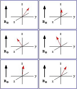
In our introduction to NMR spectroscopy we saw that application of a strong magnetic field, Bo, created two spin states of slightly different energies. Those nuclei in the lower energy state, a, have their magnetic moments aligned with Bo, while those in the higher energy state, b, have them aligned against Bo. Furthermore, there is a slight excess of nuclei in the a spin state. In our discussion of DEPT spectroscopy we represented that excess as a population difference, i.e. we set the number of nuclei in the highest energy spin state to zero and then subtracted that number from each of the spin states of lower energy. For the discussion that follows we will focus on the net magnetization, the vector sum of the individual nuclear magnetic moments, which we will represent with an arrow. It is useful to think of the orientation of that arrow in terms of a Cartesian coordinate system. Figure 1 compares these four ways of looking at nuclear magnetization. Note in View 4 that the net magnetization is aligned with the applied field. Also, it is important to understand that while Views 2 and 3 suggest that the b spin state is empty, it is not. There is simply an excess of nuclei in the a spin state.
To appreciate the fundamental nature of polarization transfer, it is necessary to understand how the net magnetization responds to the application of a second magnetic field, B1. This second magnetic field is generated by an RF coil that is wound around the x-axis, perpendicular to Bo as shown in Figure 2.
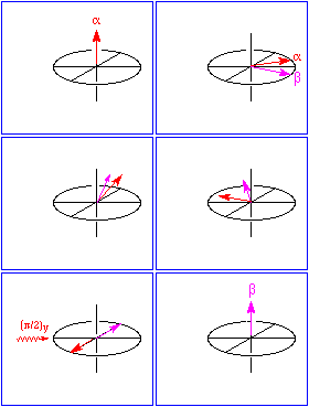
Application of B1 along the x axis tips the net magnetization vector away from the z axis towards the xy plane. The angle of the tip depends upon the length of time that current flows through the coil. This is referred to as the pulse width. By convention, pulse widths are expressed in radians; a pulse width of p/2 tips the magnetization vector by 90 degrees, i.e. from the z axis into the xy plane. A pulse width of p tips the magnetization from the +z to the -z axis. Regardless of the pulse width, once tipped, the magnetization vector precesses around the z axis. Figure 3 animates this motion.

It is important not only to understand that the magnetic moments associated with the nuclei precess around the applied field, but to realize that they precess at different rates. Furthermore, nuclei in the a spin state precess in the opposite direction of those in the b spin state.
Techniques such as DEPT and INEPT involve transferring magnetization from a sensitive nucleus such as hydrogen to a less sensitive nucleus such as carbon. The transfer occurs between nuclei that are spin-spin coupled. Each transfer technique is characterized by a particular pulse sequence. Figure 4 diagrams the INEPT pulse sequence using two alternative conventions. Figure 5 shows the response of the magnetization that pulse sequence induces.

The a and b spin states rotate away from each other at a frequency equal to J/2 Hz. The secret to a successful INEPT experiments lies in setting the delay time, tD, between pulses to appropriate multiples of the value of the coupling constant between the sensitive and insensitive nuclei. For example, after the concurrent 13C and 1H p pulses, a delay time equal to 1/(4J) seconds is required for the a and b magnetization vectors to align along the x-axis. At that point the final 1H (p/2)y pulse completes the inversion of the a and b spin states. Figure 6 outlines the spin state populations and their corresponding NMR signals before and after the pulse sequence.